A number of the pictures are now apparently not downloadable, because the hosts have disallowed
remote linking although not saying so. To view them , you have to remove the picture file name
from the picture URL and put this .htm file name in its place
and scroll down to the relevant pic.
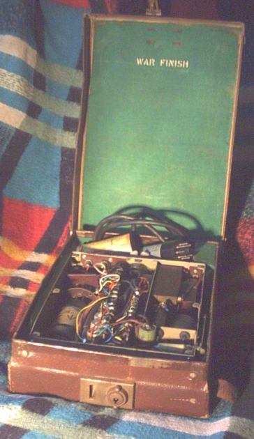
Made for ultra portability fits in an 8x12x 2.5 inch case when the thyratron
and vibrator are removed from the chassis and stowed near the hinge. What
war time use was there for such a small 'scope, with in-the-field 12V supply
capability? Thinking of ultra - almost as though it was for SOE use, repairing
behind the lines radio transmitters.
War finish presumably means the off white enamel rather than black crackle
finish. Does war finish mean whatever remnant pots of paint were around got mixed
in together ?
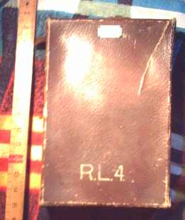
Plate on the brown casing lid
Miniscope
Miniature C/R oscilloscope
Pattern No 53259
Stencilled labels on the case are
R.L.4
and No 1
Presumably somewhere would have info on the pattern number.
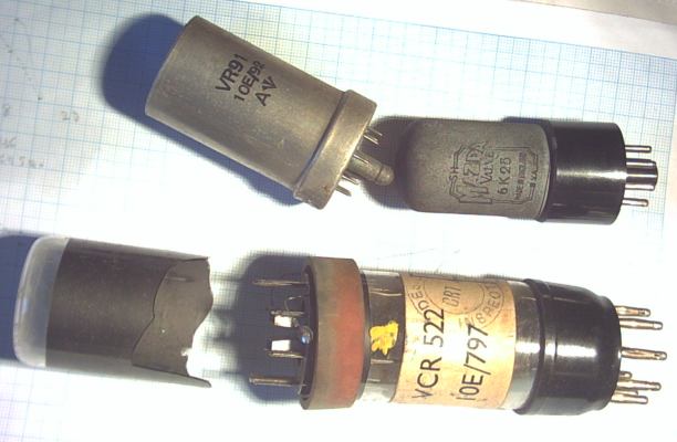
Even using "-dr who" googling does not find anything on Miniscope or that
pattern number, 6K25 thyratron , 9 pin VR91,
10E/92 and 9 pin CRT
VCR 522, 10E/787, Design Inspected CRT 4
(shattered probably when the shoulder carrying strap broke and corner brace
broke off and split occured in the "suitcase" )
no other valves,
also Masteradio G650 12V vibrator, military trident symbol in a couple of
places , after an A on the VR91 and before a Z on the CRT
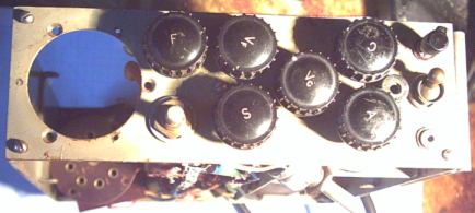
side panels and one knob missing, someone has crudely bodged in a pot where a
pin had broken off the Sync pot.
The skew aluminium cased pot is one of the things a previous owner had
done probably in 60s or 70s .
He probably added the 2 Si diodes then.
The genuine pots are very small and the original one, still
in place is broken, functionally replaced with that one , presumably the smallest he could find
but too large to fit in place. He must have given up when the carrying
strap broke and CRT cracked.
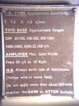
specs etc on hinge-down, prop-up plate
VR91 would seem a pentode
http://www.radiomuseum.org/tubes/tube_vr91.html
CRT some info
www.radiomuseum.org/tubes/tube_vcr522.html
apparently equivalent to CV1522 or related E4103/B/4 / CV320 / CV967 / CV335
I picked it up at a "silent key" disposal at a carboot sale. Inheritors had
no knowldege about it. The valves etc may not be what was originally in
there of course.
http://www.thevalvepage.com/testeq/gec/miniscope/miniscope.htm
GEC one looks very similar externally, especially the prop plate
The chassis dimensions are similar, this one 8 x 6.5 x 2.25 inches but
valves and internals look earlier and no built in 12V option.
I downloaded the GEC schematic from
http://www.thevalvepage.com/
but substantially different, except 4V and 6.3V heaters agree with
VCR 522 and VR91, and the aircraft power supply option, so transformer may be similar.
Of course a broken CRT makes it easy to determine pinning.
As broke unpowered the heater is still there, all 4 X,Y plates exposed and
A3 so just leaves A2 and grid undetermined without destroying the envelope
more.
155mm long, 1.5 in diam, and 7 out of 9 pins agrees with GEC E4103/B/4 with
1.1KV pda and 4V heater.
And I have the pinning for the 6K25 and pentode.
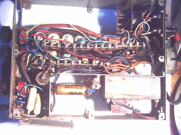
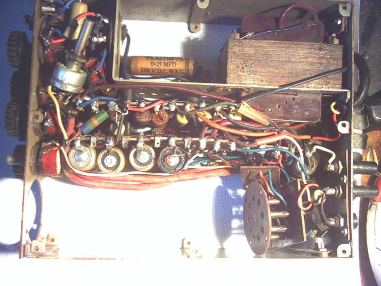
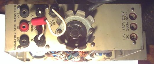
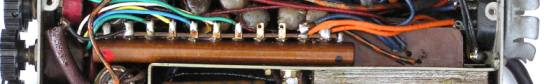
I have scanned in the board edges, as is with, and add interconnect labels , and
multi-photo before undoing and trying to unravel the schematic while trying
to find out about its likely in service use.
The black cable extending out may not be original , DC supply.
I'd thought of contacting Kew ,PRO, national archives, but the Imperial War
Museum makes sense as well.
I'm a bit concerned with the use of the word pattern before the number 53259
in that it may relate to the "samsonite" case rather than scope although
etched on to the metal plate refering to C/R oscilloscope. Perhaps there is a GEC archive somewhere other than Kew
and the war museum.
No laboratory equipment would be made deliberately too
small, requiring the removal of parts before placing in a protective
housing.
This was made to be ultra-portable, the smallest possible carrying case for
discretion, airbourne use, or covert reason, I would suggest. Routine
military equiptment is not made for the effete to carry around. Come to
think of it wartime airbourne radios etc were not made deliberately light or
compact.
There was no original probes just some home-brew croc-lead things from the
60s or 70s , of much the same date as the bodged pot.
Tested the 6K25 and the VR91 as EF50 settings and ok
Testing a Thyratron.
New one to me. 6K25 tested on an Avo CT160.
Data for 30mA, 100V settings is , under mA/V column 2K ohm.
neg grid voltage is undoubtably 4.1V, above that and meter swings below 0
and below 4.1V it swings over fsd.
What is the 2K figure, do you have to take and graph out values around the
"flash over" point ?
I should say I started with setting of 40V then 60, then 75, 90 and finally
100V. Didn't note it but the -4.1V trigger voltage appeared at 60V , I
think, and hardly changed. Just for the archives - as thyratron testing is
not very kind to test-sets. I could not decide whether to start with lower
current setting , but decided to set at the data criterion of 30mA and vary
the anode volts. Switching to test and back as quick as possible to save the
meter movement.
An email response from the guy at the valvepage site
Yes that GEC is internally quite different to mine, and the use of bigger
valves suggests an earlier design.
The catch on that case looks very un-military-like as it and the case look
so fragile.
Maybe the crt broke when the chap in the aircraft got fed up and threw the
darn thing out of the aircraft - the shaped controls on mine are still
fiddly, yet the controls on the front of yours would I think be impossible
to use with gloves on !
Also, where on earth do the valves go ? There doesn't seem to be any space,
and I also can't spot any ht rectifier.
I've seen quite a few of the GEC scopes like mine but not encountered any
like yours before so I can't really add any information. Perhaps you could
let me know if you find out more. Also, could I scrounge a couple of pics
for my website ? Just a small pic of the front and one of the side, just
enough so if a visitor sees my page they'll think "that looks just like
mine" and they can then follow a link to your page.
END
I found 2 unlabelled black painted glass Si diodes of the 70s , not original
for the added reason that 2 solder points were to wires and not tag board
tags. Se rectifiers been around since earlier than 1933 but where was there
space for any. Even if the vibrator was originally synchronous type , would
it be possible to use such a vibrator to rectifierless feed mains in , via
the transformer to such a vibrator, to allow 12V and 180/230V ac use?
The mains cable seems to go to the output side of the vibrator, with no
mechanical interlock to lockout other than someone remembering to unplug the
vibrator, or does it matter ?.
For the 4 pin vibrator, that came with it, gum on Masteradio label is bad
and original un-re-badged label under is
Mallory G650
Indianapolis Ind
Made in USA
Anyone have specs for the G650 ? or even whether synchronous types could be
in only 4 pin format
Anyone care to decode the knob legends
Vc,Vf,F,C,A,S
Vc was on the 6 way timebase switch, I am assuming it was moved from the
least used or easiest to turn without a knob
Gueses S for Sync, A for attenuation, F for Fine, C for Coarse , Vf for
focus but Vc ?
Someone else's guess
Vc is cathode voltage - probably the brilliance control
Agree Vf for focus.
F could be (timebase) Frequency?
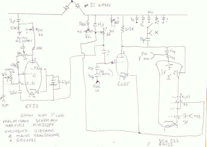
This is the preliminary node map for the scope
http://www.diverse.4mg.com/miniscope_node_map2.jpg
Scanner does not like full A4 useage.
Letters E, K and C along the top
2 tag boards running vertical, numbered from bottom S (16) and R (16) then P (11) and Q (11),
colours match major component pinning numbers to node numbers.
ground lines not added and some components around the front panel pots, switches and 2 3.5 mm i/p sockets (feintly marked as worn off , maybe read INVERT and GAIN not readable on the earlier pics) not transcribed. Some unplaced loose wires
and 2 caps covered in laquered cloth so left in place as unknown values and puffy cap values are assumed , ignoring the green and yellow "multiplier" dots that are probably temp or tolerance values.
polarised caps marked with a - .
QQ is unkown function as knob missing and other Q pot functions as letters on the knobs, as found.
There are bound to be still more errors, I've just noticed the 22K resistor apparently going to doubley N/C K6, maybe used as a tag.
M & VIB wiring and power select shorting plug arrangement is probably much like the valvepage schematic including the vib, for the later miniscope.
Power cable wiring Y,R,B is the same in both cases
Next intermediary schematic is placing the valves etc into the optimum coloured nodes and un-knotting to a certain extent.
Nothing powered up so far, a few volts from variac may resolve a few problems, and valves not tested yet.
Primary of M is probably ok , selecting 230V is 129 ohm and 180V is 75 ohm
The socket for the vib is badly fixed , one bolt is skew as it interferes with something else on the chassis. So maybe not original vib type but I don't see how a synchronous type could have made it Si diode rectifierless.
What were the smallest Se rectifiers available in the 1940s for this sort of application ?
As a circuit guide , 6K25 thyratron used in a TV frame oscillator Ultra model V815 of 1953
and EF50 pentode in 1953 Beethoven A1188 and small CRT in
Mullard 6800 with ECR36 , Cossor 1039M with 23D
and the later GEC miniscope.
What about small Selenium rectifiers that could have fitted
in the space either side of the pentode.
I have a data book , printed in 1933
Westinghouse "the all-metal way" metal rectifiers ,
how to build High Tension battery eliminators
and battery chargers.
A 300V , 60mA Westinghouse one in 1933 was about 3x3x5 inches,
no mention of Selenium, trade secret then ?.
The pic
http://www.diverse.4mg.com/Se_R.jpg
Shows on the right a disassemled one from a 1959 Dansette, one of
the two , 8 layer blocks is shown, removed, on end near the ruler (0.1 inch)
Single element rectifier
Siemens lazy S logo
Made in Germany
E 250c50
Kc 0.6e 11/16
1979 Siemens databook and E250C50 were still listed,
rating 200V, 20mA
The book page is from 1967 catalogue.
Would the English military have had access to these size
and sort of ratings, of the later rectifiers, in 1940s,
they could have been heatsinked.
I'm trying to find if any sort of (presumably) non-thermionic rectifier
could fit in a space 95x70x12 mm in the 1940s.
2 Selenium rectifier trade names of the right sort of specs, of the early
1950s, were
Westinghouse Westalite
and
STC SenTerCel
for which the earliest reference I've found is 1951.
according to ebay
http://i16.ebayimg.com/05/i/000/88/e0/2dc0_2.JPG
is a
WAR DEPT!! WESTALITE RECTIFIER,NORTON, TRIUMPH, MATCHLESS etc... Straight
from the War Department.
Genuine NOS Military parts removed from 'jungle paper'
Rectifier Made in England By Westinghouse Brake & Signal Co Ltd. Pat 620102
& others. Cat No. 2L 985.
Positive Case. 98mm x 98mm x 12mm.
When did "war dept" cease ?
http://www.wikipatents.com/gb/0620102.html
for UK patent 620102, 1947, is about rectifier construction/gaskets but
refers to "well known selenium type"
So compact , presumably low V, high A for motorcycle use in war time
but what about high V, low A , compact multiplate rectifier in early 1940s ?
Another example of early miniaturisation , from Germany
The Minifon P55 wire recorder with 5 hours record possibility, uses 2x DF67 and a DL67 apparently
"Walkman" Size 1 9/16 x 3 15/16 x 6 11/16 inches , 2 lbs
Scanned in image from the 1956 version of the book in the heading, with
preceeding lines inserted over the top, correction 3 batteries
http://www.diverse.4mg.com/minifon.jpg
preliminary schematic
Will have to check the top left HT rail cap wiring, noticed since plotting out.
Anyone know of an E4103/B/4 or compatible CRT around the UK ?
I quite often see similar at radio rallies. Will make do with a 2 inch one
, Telefunken DG 7 32 strangely maybe the same as Mullard DG7 32, poking out the front
From someone at the Defence Electronics History Society ,Shrivenham
, 180v 500Hz is a standard Navy power cct for Navy not the RAF.
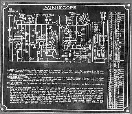
Update August 2009
Ron in Lancashire picked up a complete one at a radio rally.
One of the side panels has the circuit diagram and parts list etched on, of which he sent me a pic
negative version which is clearer to read. Includes 2 Selenium rod
type HT rectifiers "H55" ? (no info found on H55, H10 were metal
rectifiers made by Westinghouse
probably no more than 100V rating, available about 1943 to 1947 ) , one of them shown here
His also has the brown carrying case.
From his researches
"it (this miniscope) was used
in the Royal Navy/ Fleet Air Arm in connection with tone modulation
frequency tests on sonobuoys that were dropped and then monitored by Fairey
Gannet aircraft. This was an anti submarine operation until superseded by
helicopters and their dipping listening devices."
From his contacting the journal, there will be a future
item published in Practical Wireless (sometime after September 2009).
If this email address fails then replace onetel.com with fastmail.fm or
replace onetel.com with divdev.fsnet.co.uk part of the address and
remove the 9 . Please make emails plain text only , no more than 5KByte or 500 words.
Anyone sending larger texts or attachments such as digital signatures, pictures etc will have
them automatically deleted on the server. I will be totally unaware of this, all your email will be deleted - sorry, again
blame the spammers. If you suspect problems emailing me then please try using
my fsnet.co.uk account.
Diverse Devices, Southampton, England
electronic hints and repair briefs , schematics/manuals list To return to main Diverse Devices site
http://home.graffiti.net/diverse